AOS-A40DL
Product introduction:
Product overview
The motherboard is based on the Allwinner A40i high-performance quad-core application processor platform.
The A40i main chip integrates a quad-core Cortex-A7 and a Mali-400 MP2 high-performance GPU, with a maximum frequency of 1.2GHz.
It has super computing performance, 2D/3D graphics processing capabilities and full HD video encoding and decoding capabilities, and perfectly supports 1080p@45fps HD decoding and 1080p@60fps HDMI HD output.
Its industrial quality standards can support operating temperatures of -40℃~85℃.
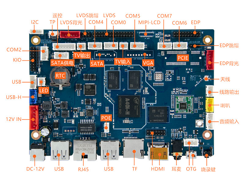
Specification List
功能&接口 Function & Interface | 详细描述 Detailed Description |
CPU | 全志Cortex-A7四核,最高主频1.2GHz Allwinner Cortex-A7 quad-core, up to 1.2GHz |
DDR | DDR3 1GB(2GB可选) DDR3 1GB (2GB optional) |
存储 Storage | 默认标配8GB EMMC NAND芯片,可扩展至最大128GB The default comes with an 8GB EMMC NAND chip that can scale up to 128GB |
LVDS | 30针行业标准双路LVDS接口,支持VESA/JEITA格式,最高支持1080P输出 30-pin industry-standard dual LVDS supporting VESA/JEITA format up to 1080P output |
HDMI输出 HDMI Output | HDMI 2.0标准显示接口,最高支持1080P输出 HDMI 2.0 standard display interface supports up to 1080P output |
MIPI-DSI | 31-Pin FPC MIPI-DSI显示接口(选配),最高支持1920x1200输出 31-Pin FPC MIPI-DSI display port supporting (optional), up to 1920x1200 |
EDP | 20针行业标准双路EDP接口(eDP 1.4),支持1~4通道模式,最高支持1080P输出 20-pin industry-standard EDP (eDP 1.4) supporting 1~4 lanes format up to 1080P output |
VGA输出 VGA Output | VGA 9芯排针接口(选配),最高支持1080P输出 9-pin header VGA output up to 1080P (optional) |
线路输出 Line Output | 支持标准左右声道线路输出(排针接口) Support standard left and right channel line output (pin header) |
耳机/麦克 HP/MIC | 支持美标4段耳麦一体3.5mm插座(左-右-地-麦克) Support CTIA 4-pole HP/MIC socket (Left-Right-GND-Mic) |
功放输出 Amplifier output | 8欧・6W双路音频功放输出 8 Ohm 6W Dual Audio Amplifier Output |
MIC输入 MIC Input | 差分MIC输入(排针接口) Differential MIC input (pin header) |
线路输入 Line Input | 支持标准左右声道线路输入(排针接口) Support standard left and right channel line input (pin header) |
USB 2.0接口 USB 2.0 Interface | 2个外置横插接口(单层插座),2个内置排针,1个OTG排针 2 horizontal connectors (Single Socket), 2 pin headers, 1 OTG pin header |
串口 Serial Port | 2个TTL/RS-485兼容内置,4个TTL/RS-232兼容内置 2 TTL/RS-485 compatible, 4 TTL/RS-232 compatible |
TF卡 Micro SD Card | 自弹式TF卡插座,最高支持256GB TF卡 Self-elastic micro SD card socket, up to 256GB capacity |
摄像头 Camera | 支持200万像素以内USB摄像头 Support USB camera within 2 million pixels |
WiFi | 内置高性能XR829 WiFi模块,支持IEEE 802.11 b/g/n Built-in high performance XR829 WiFi module, support IEEE 802.11 b/g/n |
蓝牙 Bluetooth | 内置高性能USB接口BT模块,支持V2.1+EDR/BT v3.0/BT v3.0+HS/BT v4.2 Built-in high performance USB interface BT module with support for V2.1+EDR/BT v3.0/BT v3.0+HS/BT v4.2 |
以太网口 Ethernet | 10/100M自适应以太网RJ45网口 + 4芯POE供电排针 10/100M Adaptive Ethernet RJ45 connector + 4-Pin POE PD header |
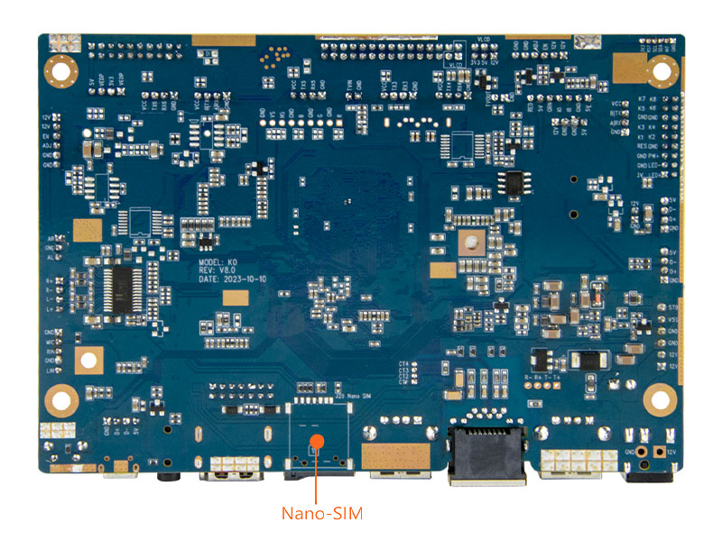
Mini PCI-E 4G | 行业标准Mini PCI-E 4G模块接口(选配),支持Nano-SIM卡插槽 Industry standard Mini PCI-E 4G module interface (optional) with Nano-SIM card socket |
背光控制 Backlight Control | 2路行业标准液晶屏背光控制接口(LVDS和EDP),支持背光开关和亮度调节 2 port Industry standard LCD backlight control header for LVDS & EDP, support for backlight switch and brightness adjustment |
红外遥控 Infrared RC | 标准红外接收排针接口 Standard infrared receiver pin header |
GPIO信号 GPIO Signals | 8路GPIO信号,可扩展GPIO按键和/或3.3V输入/输出 8-way GPIO signals for such as GPIO buttons and/or 3.3V digital input/output |
TV输入 TV Input | 1路CVBS输入信号 1-way CVBS Input Signal |
TV输出 TV Output | 1路CVBS输出信号 1-way CVBS Output Signal |
I2C总线 I2C Bus | I2C排针和FPC接口,可扩展I2C电容屏等 I2C pin header and FPC for I2C capacitive screen and etc |
SATA硬盘 SATA HD | 标准SATA 2.0硬盘接口(选配) Standard SATA 2.0 hard disk port with power supply header (optional) |
实时时钟 Real Time Clock | 超低功耗RTC电路(带CR1220纽扣电池),并可支持定时开关机 Ultra-low-power RTC circuit (CR1220 battery) with timer and alarm functionalities |
指示灯 LED Indicator | 红色待机指示和绿色工作指示灯 Red LED indicator for standby and green LED indicator for running |
按键 Buttons | 烧录键(RECOVERY)和电源键 Recovery mode button and power switch button |
电源输入 DC Input | 支持9~15V宽电压直流电源输入 Supports 9~15V wide voltage DC power input |
环境要求 Ambient Requirement | 工作温度-20°C ~ 70°C,工作湿度0%~95%(不结露) Working temperature -20°C ~ 70°C, working humidity 0%~95% (non-condensing) |
物理尺寸 Physical Size | 长*宽*高(135mm*93mm*11mm),PCB正面高度7.5mm Length*Width*Height (135mm*93mm*11mm), PCB top side height 7.5mm |
安卓系统 Android Version | 推荐Android 7.1 Recommended Android 7.1 |
Physical Size
